8.3 Road reference line coordinate systems
The road reference line is always located within the x/y plane defined by the inertial coordinate system.
A road reference line coordinate system runs along the road reference line.
It is a right-handed coordinate system.
The s-axis follows the tangent of the road reference line.
The t-axis is orthogonal to the s-axis and may be rotated around the s-axis by superelevation.
The right-handed coordinate system is completed by defining the up-direction h orthogonal to s-axis and t-axis.

Figure 13 shows the degrees of freedom defined for the road reference line coordinate system.
The following degrees of freedom are defined:
s |
coordinate along road reference line, measured in [m] from the beginning of the road reference line, calculated in the x/y plane (that is, not taking into account the elevation profile of the road) |
t |
lateral position, perpendicular to the road reference line and angled relative to the x/y plane according to the road superelevation. Positive to the left of the road reference line. |
h |
orthogonal to s/t plane in a right-handed coordinate system |
heading |
rotation around h-axis |
superelevation |
rotation around s-axis |

Figure 14 shows the different states of a road reference line coordinate system with defined rotations.
Similar to the inertial coordinate system, the s’/t’/h’ and ssuperelevation/tsuperelevation/hsuperelevation denote the rotated coordinate systems around heading and superelevation angle.

Figure 15 shows how the road reference line coordinate system can be positioned in the inertial space by providing the origin’s coordinates and the orientation (heading) of the origin with respect to the inertial coordinate system.
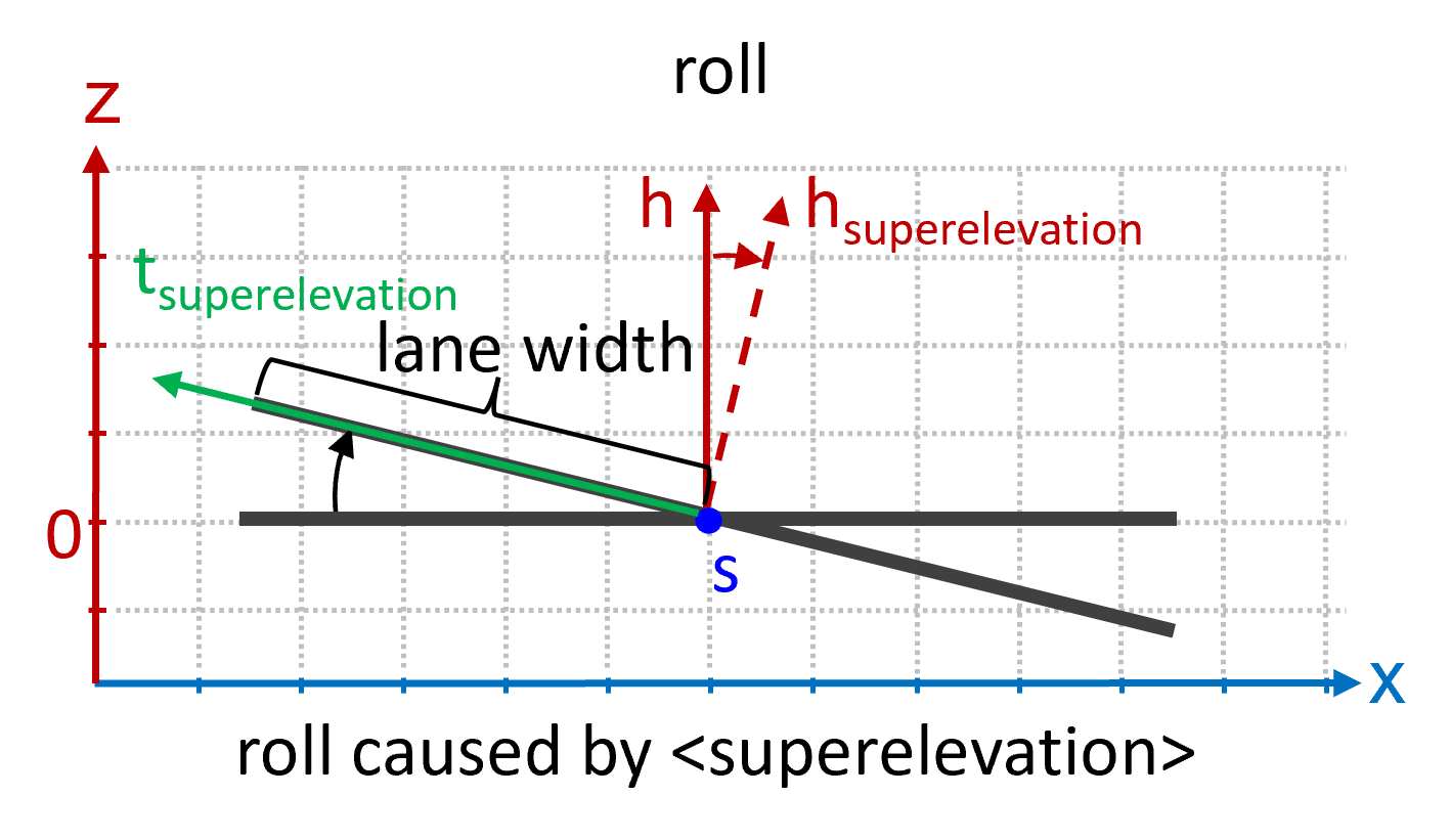
Figure 16 shows how superelevation causes a roll in the road reference line. Values of t are measured in the superelevated lane. The value of the @width attribute of the lane does not change if superelevation is applied. The projected width in the x/y plane is different to the width of the superelevated lane.

Figure 17 shows the elevation for road reference line coordinate systems. For the s/t/h coordinate system no pitch is possible. Elevation has no effect on the length of s.
|
In ASAM OpenDRIVE, objects and signals are placed in their own s/t-coordinate system and are not rotated by superelevation, they specify their position relative to the road reference line and then can be rotated individually.
Their @t attribute is rotated with the lane affected only by superelevation, so an object or signal placed at the border of a lane stays at this border regardless of superelevation or not.
Their @zOffset attribute is calculated in z-direction, a value of |